Introduction
The Shape & Materials panel defines the external physical shape of the spacecraft as it is represented inside SatModeler. This panel is dedicated to importing, inspecting, and editing spacecraft geometry, as well as assigning and tuning surface materials at element level.
Unlike abstract or lumped-parameter models, this panel exposes the spacecraft as a collection of explicit surface elements. Users can directly interact with these elements, remove or isolate them, and control their visual and material properties with fine granularity.
This panel always operates on the Shape Mesh, which is the visible geometric representation of the spacecraft inside the simulator. It is the reference geometry used for visualization, element selection, and material assignment, and it provides a clear and intuitive way to understand how the spacecraft is built up from individual surfaces.
The Geometry & Materials panel is therefore the primary interface for defining what the spacecraft looks like and how its surfaces are characterized, independently of how environmental forces and torques are later computed.
Geometry Import
Supported geometry formats
SatModeler supports importing external spacecraft geometry using the following formats:
- OBJ
- ASCII STL
These formats are intended to cover the majority of CAD-to-simulation workflows while maintaining predictable behavior and robustness.
OBJ material handling (important)
When importing an OBJ file, material information is loaded from an associated .mtl file. For materials to be correctly imported, the following conditions must be satisfied:
- The
.mtlfile must be located in the same directory as the.objfile - The
.mtlfile must have the same base filename as the.objfile - The material file must use the
.mtlextension
Example:
satellite.obj
satellite.mtlIf any of these conditions are not met, the OBJ geometry will still be loaded, but materials will not be imported, and a default material will be assigned instead.
Material behavior by format
- OBJ
- All materials defined in the
.mtlfile are imported and listed - If no materials are defined, a single default material is created
- All materials defined in the
- ASCII STL
- STL files do not contain material information
- A single default material is always created automatically
Shape Mesh and Its Role
The Shape Mesh represents the spacecraft as seen by the user:
- It is the fully detailed, visible geometry
- It supports high geometric complexity
- It is used for visualization, inspection, and interaction
The Shape Mesh is not directly used to compute environmental perturbations. Instead, SatModeler can derive (if the user uses this option) a separate Perturbation Mesh from it, optimized for force and torque evaluation.
This separation allows:
- Visually detailed spacecraft models
- Physically efficient and numerically stable perturbation computation
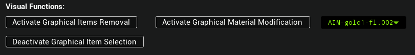
Graphical Interaction Modes
The Geometry & Materials panel provides three dedicated graphical interaction modes that allow direct manipulation of the Shape Mesh from the 3D view. Each mode focuses on a specific type of operation and is explicitly activated and deactivated by the user.
Only one mode is intended to be used at a time.
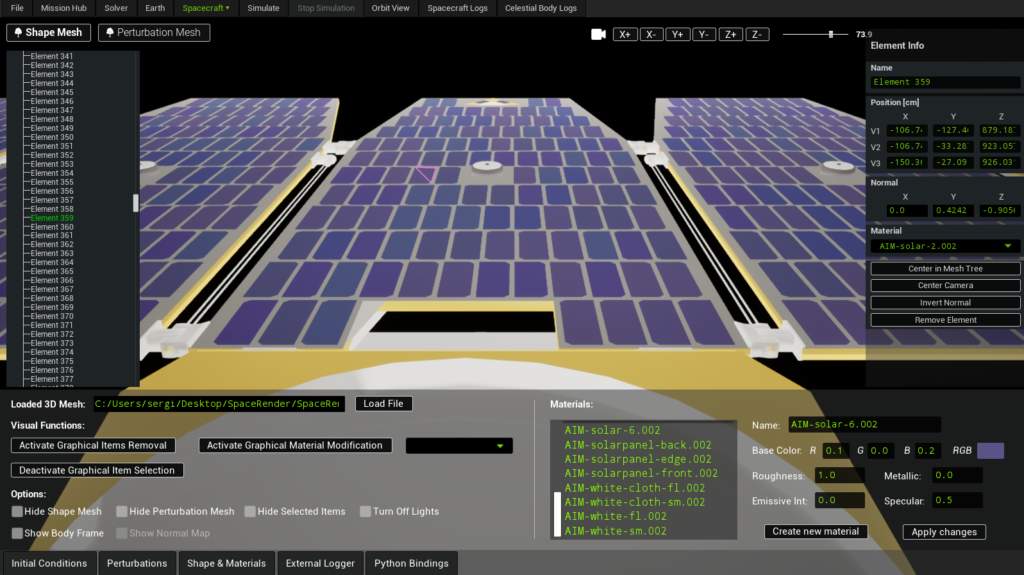
Graphical Item Selection
This mode allows precise selection of individual mesh elements directly in the 3D viewport.
To activate this mode, press Activate Graphical Item Selection. Once active, simply click on the desired mesh element in the 3D view.
The selected element will:
- Be visually highlighted in the scene
- Appear in the right-hand Element Info panel
- Become available for inspection and modification (position, normal, material assignment, etc.)
To exit this mode, press Deactivate Graphical Item Selection.
Graphical Item Removal
This mode enables the permanent removal of mesh elements from the Shape Mesh using an interactive selection area.
To activate this mode, press Activate Graphical Item Removal. A green circular selection area will appear in the 3D view.
Operation details:
- The radius of the green circle can be increased or decreased using Ctrl + mouse scroll up/down
- It is essential that no unintended elements are present behind or intersecting the circle
- Any element intersecting the selection volume, including elements located behind the visible surface, will also be removed
Once the intended elements are isolated within the circle, press Ctrl + Shift to confirm removal.
Important notes:
- The operation is computationally expensive
- Processing time may reach several seconds, depending on mesh complexity
- Removed elements are permanently deleted from the Shape Mesh
This mode should be used carefully, especially on dense or layered geometries, to avoid accidental removal of valid surfaces.
To exit this mode, press Deactivate Graphical Item Removal.
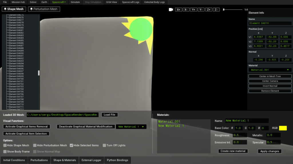
Graphical Material Modification
This mode allows interactive reassignment of materials to mesh elements directly in the 3D view.
To activate this mode, press Activate Graphical Material Modification and select the desired material from the available materials list before proceeding. Once active:
- A green circular selection area appears, identical in behavior to the removal mode
- The circle radius is adjusted using Ctrl + mouse scroll up/down
- All elements intersecting the circle will have their material changed
- This includes elements that may be occluded, internal, or located behind the visible surface
For this reason, it is critical to ensure that the green selection area contains only the elements that are truly intended to be modified, and that no additional geometry lies behind them along the view direction.
Important notes:
- The operation is computationally expensive
- Processing time may reach several seconds, depending on mesh complexity
- Modified elements will be moved in the Shape Tree, according to the newly assigned material
This mode is particularly powerful for rapid material reassignment, but requires careful camera positioning and selection control to avoid unintended changes.
To exit this mode, press Deactivate Graphical Material Modification.
Visualization Options
A set of visualization and diagnostic options is available to control how geometry is displayed and inspected:

- Hide Shape Mesh
Toggles visibility of the Shape Mesh. - Hide Perturbation Mesh
Toggles visibility of the Perturbation Mesh, allowing direct inspection of the geometry used for force and torque computation. - Hide Selected Items
Temporarily hides all currently selected Shape Mesh elements. - Turn Off Lights
Disables scene lighting.
This is particularly useful when inspecting emissive materials, as their contribution becomes visible without external illumination. - Show Body Frame
Displays the spacecraft body reference frame, useful for orientation checks and debugging. - Show Normal Map
Visualizes surface normals of the Perturbation Mesh only.
This option does not affect the Shape Mesh and is intended purely for diagnostic purposes.
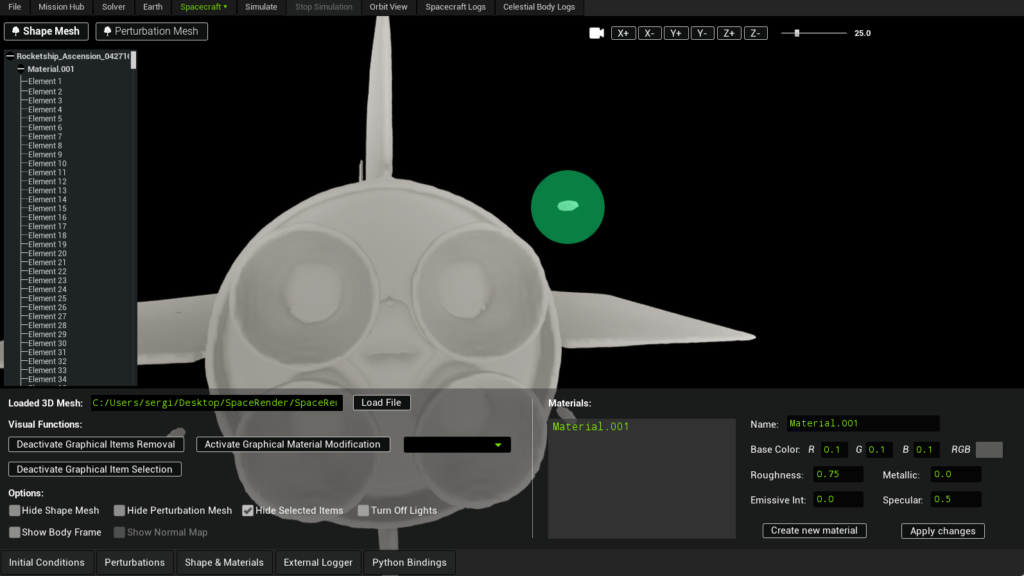
Materials
Material list
All materials currently loaded in the workspace are listed in the materials panel on the right:
- For OBJ imports, all materials defined in the
.mtlfile appear - For STL imports, a single default material is shown
Materials can be edited independently and applied to any number of mesh elements. New materials can also be created and assigned to existing elements.
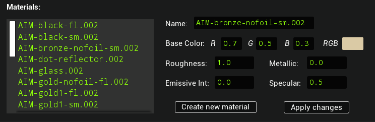
Material Parameters
Each material exposes the following parameters:
- Base Color (RGB)
Defines the visible color of the surface.
Affects visual appearance and consistency across different lighting conditions. - Roughness
Controls surface micro-roughness.
Low values produce smooth, glossy surfaces; high values produce matte surfaces. - Metallic
Defines whether the surface behaves optically like a metal.
Influences reflectivity and energy conservation in shading. - Specular
Controls the intensity of specular reflections for non-metallic materials. - Emissive Intensity
Causes the material to emit light independently of scene lighting.
Useful for active components and for inspection when lights are disabled.
Material changes are applied in real time and immediately reflected in the 3D view after the user clicks on the “Apply Changes” button.