Introduction
In an ideal two-body problem, a spacecraft follows a perfectly predictable Keplerian orbit and its attitude remains unaffected unless actively controlled. Real missions never operate under such ideal conditions.
The Perturbations panel defines all additional forces and torques that act on the spacecraft beyond the central gravitational attraction. These effects may appear small at a single time step, but their cumulative impact often dominates long-term orbit evolution and attitude behavior.
SatModeler includes a comprehensive set of perturbation models, some of which may have a minor influence for specific missions. They are nevertheless implemented to allow users to reach the maximum achievable physical fidelity and to let mission designers decide, case by case, which effects are relevant for their objectives.
Perturbations
Perturbations Selection Panel
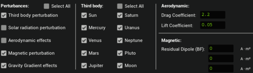
This panel acts as the global switchboard for all non-ideal effects. Each checkbox enables or disables a specific physical model at spacecraft level.
If a perturbation is disabled here, it is completely excluded from the equations of motion, regardless of any parameters defined elsewhere.
Third-Body Perturbation
Physical meaning
The two-body approximation assumes that the spacecraft is influenced only by the central body (typically Earth). In reality, every massive body in the Solar System exerts a gravitational pull. While most of these forces are small compared to Earth’s gravity, they are systematic and continuous, and therefore accumulate over time.
Bodies included in SatModeler
SatModeler allows third-body perturbations from all major Solar System bodies:
- Sun
- Moon
- Mercury
- Venus
- Mars
- Jupiter
- Saturn
- Uranus
- Neptune
- Pluto
Each body can be enabled or disabled independently.
Why this matters
- For LEO missions, third-body effects are often dominated by the Sun and Moon.
- For high-altitude orbits, lunar and solar perturbations can significantly alter orbital elements.
- For long-duration simulations, even small planetary contributions improve numerical realism.
SatModeler models these effects not because they are always dominant, but because excluding them artificially limits achievable accuracy.
How it is applied
- Translational force only (no torque)
- Does not require a perturbation mesh
- Computationally inexpensive relative to other perturbations
Solar Radiation Pressure (SRP)
Physical meaning
Photons carry momentum. When solar radiation impacts a spacecraft surface, momentum exchange produces a force. If the force does not act through the center of mass, a torque is also generated.
For spacecraft with large surface-to-mass ratios, such as those with solar arrays or deployable structures, SRP can be a dominant non-gravitational disturbance.
Why this matters
- SRP can cause measurable orbital drift, especially in high-altitude orbits
- SRP torques affect attitude stability and control authority
- Effects grow with exposed area and mission duration
How SatModeler computes SRP
Forces and torques are computed per element of the perturbation mesh.
Each element contributes based on:
- Area
- Orientation relative to the Sun
- Position relative to the spacecraft center of mass
The contributions are summed to obtain the total force and torque acting on the spacecraft.
Important behavior
- Disabled by default
- Automatically ignored if no perturbation mesh exists
- Requires a perturbation mesh to be defined
Visualization
SRP forces and torques can be visualized in the Orbit View workspace, allowing direct inspection of their magnitude.
Aerodynamic Effects
Physical meaning
In low Earth orbit, the spacecraft moves through a rarefied but non-zero atmosphere. Collisions with atmospheric particles produce aerodynamic forces and torques.
These effects depend strongly on:
- Atmospheric density
- Spacecraft velocity
- Spacecraft geometry and orientation
Drag and Lift
Aerodynamic forces acting on a spacecraft can be decomposed into drag and lift components relative to the atmospheric flow.
Drag is the force component opposing the relative velocity of the spacecraft with respect to the atmosphere. Its primary effect is the dissipation of orbital energy, which leads to a gradual reduction of the spacecraft’s semi-major axis and results in progressive orbital decay.
Lift is the force component perpendicular to the relative velocity vector. It arises when the spacecraft geometry and attitude are asymmetric with respect to the flow. Unlike drag, lift does not necessarily act to dissipate orbital energy and can produce a variety of dynamical effects.
Depending on the spacecraft orientation and flight regime, lift can:
- Modify multiple orbital elements, including inclination and eccentricity
- Generate cross-track and in-plane accelerations
- Produce attitude-dependent torques
In certain mission scenarios, lift can even be intentionally exploited through attitude control to influence orbital evolution.
The aerodynamic model includes the following user-defined coefficients:
- Drag coefficient
- Lift coefficient
These coefficients are global and are applied uniformly to all elements of the perturbation mesh.
How SatModeler computes aerodynamic effects
- Forces and torques are computed per perturbation mesh element
- Geometry-dependent and attitude-dependent
- Uses atmospheric density provided by the Earth workspace
Important behavior
- Disabled by default
- Requires a valid perturbation mesh
- Automatically disabled if no mesh exists
Visualization
Aerodynamic forces and torques can be visualized in the Orbit View workspace.
Magnetic Perturbation
Physical meaning
Spacecraft are rarely magnetically neutral. Residual magnetization arises from onboard electronics, wiring, and structural materials. When this residual magnetic dipole interacts with the planetary magnetic field, a torque is produced.
Why this matters
- Magnetic torques can dominate passive attitude dynamics in small satellites
- Especially relevant for CubeSats and detumbling scenarios
- Can interfere with precision pointing
How it is applied
- Torque only (no force)
- Based on the user-defined residual magnetic dipole vector
- Does not require a perturbation mesh
This perturbation directly couples the spacecraft attitude to the Earth’s magnetic field model selected in the Earth workspace. If attitude dynamics are not of interest, this perturbation can be safely disabled.
Gravity Gradient Effects
Physical meaning
Gravity decreases with distance. For extended spacecraft, different parts of the structure experience slightly different gravitational accelerations, producing a torque that tends to align the spacecraft with the local vertical.
Why this matters
- Relevant for elongated or asymmetric spacecraft
- Can be exploited for passive attitude stabilization
- Can interfere with active control systems
How it is applied
- Torque only
- Depends on spacecraft mass distribution and orbital position
- No user parameters required in this panel
If attitude dynamics are not of interest, this perturbation can be safely disabled.
Typical Magnitude and Relevance of Perturbations
| Perturbation | Order of magnitude | Primarily affects | When it should be enabled |
|---|---|---|---|
| Third body | 10⁻⁷ – 10⁻⁶ m/s² | Orbit | High-altitude orbits, long-duration simulations, precision orbit analysis |
| Solar radiation pressure | 10⁻⁸ – 10⁻⁶ m/s² | Orbit & attitude | Large surface-to-mass ratio, GEO and beyond, attitude-sensitive missions |
| Aerodynamic forces | 10⁻⁶ – 10⁻⁴ m/s² | Orbit & attitude | LEO missions below ~800 km altitude |
| Magnetic torque | 10⁻⁸ – 10⁻⁵ N·m | Attitude | Small satellites, detumbling, passive attitude analysis |
| Gravity gradient | 10⁻⁸ – 10⁻⁶ N·m | Attitude | Extended spacecraft, passive stabilization studies |
Force-related perturbations are expressed as specific forces (m/s²), i.e. forces normalized by spacecraft mass, to allow direct comparison across spacecraft masses.
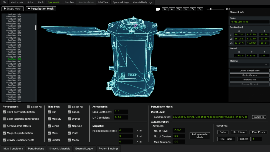
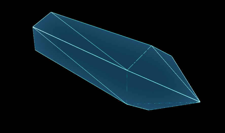
Perturbation Mesh
The Perturbation Mesh defines the geometric representation used internally by SatModeler to compute geometry-dependent perturbations, specifically:
- Solar radiation pressure forces and torques
- Aerodynamic forces and torques
Unlike point-mass or lumped-parameter models, these perturbations are evaluated at the level of individual surface elements, allowing forces and torques to be generated naturally from the external geometry of the spacecraft.
The perturbation mesh is one of the defining features of SatModeler. It allows users to move beyond simplified point-force models and explicitly link spacecraft geometry to environmental disturbances. While optional, this capability enables research-grade and high-fidelity simulations when required, giving users full control over the trade-off between physical realism and computational efficiency.
Role in the Simulation
The perturbation mesh represents the spacecraft as seen by the environment, not as seen by the user visually. It is:
- Independent from the Shape Mesh
- Used exclusively for force and torque computation
- Evaluated at every simulation time step when SRP or aerodynamic perturbations are enabled
If no perturbation mesh is defined:
- Solar radiation pressure is automatically disabled
- Aerodynamic effects are automatically disabled
This behavior prevents the use of incomplete or physically inconsistent models.
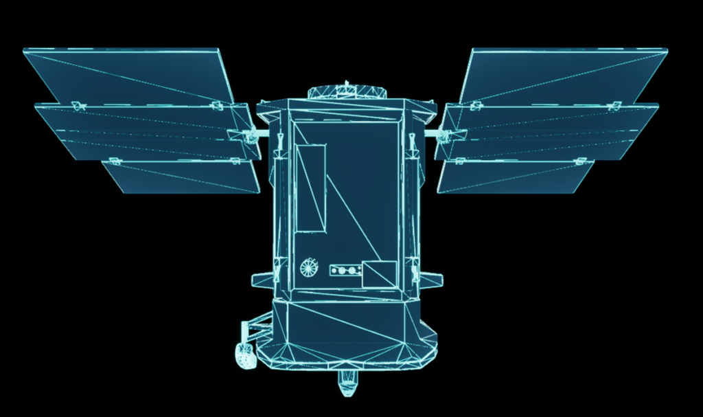
Shape Mesh vs Perturbation Mesh
SatModeler intentionally separates spacecraft geometry into two distinct representations:
- Shape Mesh
- Used for visualization
- Can be highly detailed
- Has no direct impact on perturbation computation
- Perturbation Mesh
- Used for SRP and aerodynamic calculations
- Typically simplified
- Optimized for physical accuracy and computational efficiency
This separation allows users to maintain a visually detailed spacecraft while independently controlling the level of fidelity used for force modeling.
Editing and Interaction
The perturbation mesh is fully editable.
Key interaction features:
- Dedicated geometry tree for the perturbation mesh
- Element-level editing via the right-hand properties panel
- Graphical selection of mesh elements directly in the 3D view
This workflow enables precise control over:
- Element position and orientation
- Effective area
- Contribution to force and torque generation
SatModeler provides multiple ways to create a perturbation mesh, allowing users to choose the appropriate balance between accuracy, effort, and computational cost.
Loading an External Mesh
A perturbation mesh can be loaded from an external file.
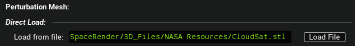
Key requirements:
- Only ASCII STL files are supported
- Binary STL files are not accepted
This option is intended for users who:
- Generate simplified force models externally
- Use CAD-derived meshes specifically prepared for perturbation analysis
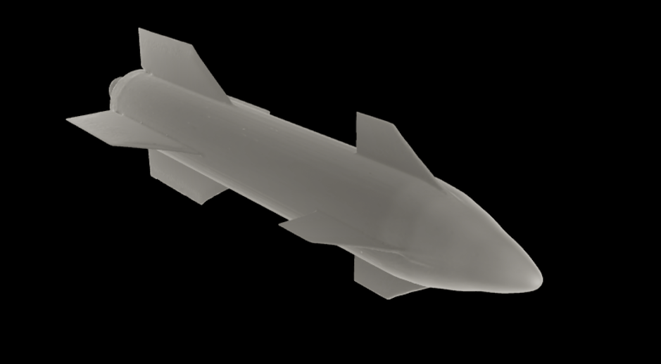
Primitive-Based Construction
Perturbation meshes can be built directly from geometric primitives:
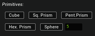
- Cube
- Square-base prism
- Pentagonal prism
- Hexagonal prism
- Sphere (with user-defined resolution)
Primitive-based meshes are particularly useful for:
- Early design phases
- Sensitivity studies
- Performance-oriented simulations
They allow users to capture the dominant geometric characteristics of a spacecraft with minimal computational overhead.
Automatic Generation from Shape Mesh
For complex spacecraft geometries, SatModeler can automatically estimate a perturbation mesh from an existing shape mesh.
This process samples the external geometry and generates a simplified surface representation suitable for force computation.
Why this feature exists
Highly detailed shape meshes are often:
- Computationally impractical for per-element force evaluation
- Poorly suited for aerodynamic or SRP modeling without simplification
The automatic generation algorithm provides a practical bridge between visual fidelity and physical accuracy.
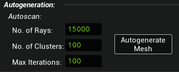
The quality and cost of the generated perturbation mesh are controlled by three parameters:
Number of rays
Controls how densely the external geometry is sampled.
- Higher values improve capture of fine geometric features
- Increasing this parameter has a moderate impact on computation time
Number of clusters
Controls the effective number of surface elements generated in the perturbation mesh.
- Strongly influences the number of force and torque contributions evaluated at each time step
- Has the largest impact on computational cost
- Should be chosen carefully for long simulations
Number of iterations
Controls the convergence of the approximation process.
- Higher values improve fidelity for a given number of rays and clusters
- Has a relatively small impact on runtime compared to the number of clusters
Increasing any of these parameters improves accuracy but increases computational cost. In practice, the number of clusters is the dominant driver of performance.
Normals and Mesh Validity
Surface normals define the outward direction of each mesh element. For any geometry-dependent perturbation, the normal direction is critical because it determines:
- Which surfaces are considered illuminated by the Sun (SRP)
- Which surfaces face the incoming atmospheric flow (aerodynamics)
- The sign and direction of the resulting force and torque contributions
If a significant portion of the perturbation mesh has flipped or inconsistent normals, the computed SRP/aerodynamic forces may be underestimated, overestimated, or even partially cancelled by incorrect contributions.
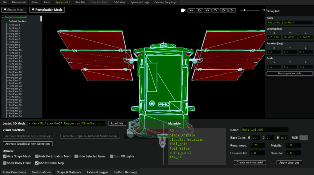
Visual verification using the Normal Map
SatModeler provides a visual aid in the Shape & Materials panel to help inspect the orientation of surface normals.
Enable Show Normal Map to visualize the orientation of the mesh surface using color coding.
In this view:
- Green areas indicate surfaces whose normals generally point away from the spacecraft body, as expected for external geometry.
- Red areas indicate surfaces whose normals are not oriented outward, meaning they point inward or sideways relative to the spacecraft body.
This visualization helps you quickly identify areas that may require attention after importing or editing geometry.
This tool is intended as a visual inspection aid, not as a strict geometric validator.
Red areas do not automatically mean the geometry is wrong. On concave shapes, recessed regions, or complex spacecraft geometries, some surfaces may appear red even if they are valid.
- Enable Show Normal Map to display the surface normals across the mesh.
- Inspect the spacecraft exterior and verify that normals are consistently oriented outward.
This check is recommended after:
- Importing a perturbation mesh from an external STL (ASCII) file.
- Performing manual edits that can modify local topology
Accuracy vs Performance Considerations
The perturbation mesh is a high-accuracy feature, but it is not always required.
It is most relevant when:
- Solar radiation pressure or aerodynamic torques are critical
- Spacecraft geometry is highly asymmetric
- Attitude dynamics are sensitive to external disturbances
- Long-duration simulations are performed
For missions where:
- Only translational motion is of interest
- The spacecraft can be approximated as symmetric
- Computational speed is the priority
a simplified or primitive-based perturbation mesh is often sufficient.