Overview
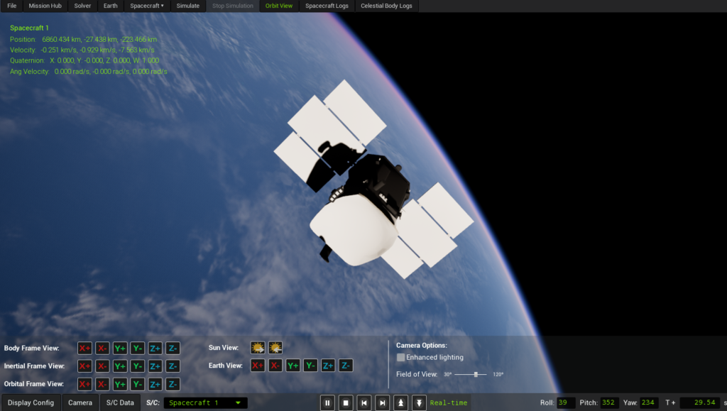
The Orbit View workspace is the primary 3D visualization and analysis environment in SatModeler. It allows users to inspect the orbital motion, attitude, reference frames, and external perturbations acting on spacecraft throughout the simulation timeline.
Visualization settings and geometry changes are applied immediately in Orbit View. However, any modification affecting spacecraft motion or dynamics must be simulated before the resulting behavior can be displayed.
Orbit View is designed for users who need to:
- Correlate orbital motion, attitude dynamics, and environmental interactions in a single, physically consistent 3D scene
- Inspect spacecraft orientation simultaneously in body, inertial (J2000), and orbital reference frames, and understand their relative evolution over time
- Visually analyze external perturbations at mesh level, including solar radiation pressure and aerodynamic forces, mapped directly onto the spacecraft geometry
- Validate attitude laws, pointing strategies, and frame conventions by observing real-time vector alignment (Sun, velocity, nadir, angular velocity)
- Explore spacecraft behavior across the full simulation timeline using interactive time scrubbing, playback control, and deterministic state reproduction
Visibility requirement
Even if a mission is simulated correctly, the Orbit View workspace is only available if all spacecraft in the mission have a valid shape mesh defined.
If one or more spacecraft do not include a shape mesh, Orbit View will not be displayed, as the workspace relies on geometric models to render spacecraft, reference frames, vectors, and perturbation meshes consistently.
This requirement ensures that all visual elements shown in Orbit View are physically meaningful and correctly aligned with the spacecraft geometry.
Main Features
Toolbar
The toolbar provides global control over the visualization and simulation playback.

It contains:
Expandable submenus
- Display Config
- Camera
- S/C Data
These submenus expose detailed visualization settings described in the following sections.
Playback controls
- Pause the visualization
- Reset to the beginning of the simulation
- Jump to the end of the simulation
- Increase or decrease playback speed
Camera orientation controls
- Roll, Pitch, and Yaw values are displayed numerically
- Mouse wheel controls camera zoom in and zoom out
- Orientation can be modified using on-screen controls
- Keyboard shortcuts are also supported:
- Left / Right arrows → Roll
- Up / Down arrows → Pitch
- A / D keys → Yaw
Time control
- The current simulation time is displayed in the toolbar
- Time can be edited directly to jump to a specific instant in the simulation
Display Config Menu
The Display Config submenu controls which visual elements are rendered in the 3D scene.

Reference frame display (checkboxes)
- Show spacecraft Body frame axes
- Show spacecraft Inertial frame axes (J2000)
- Show spacecraft Orbital frame axes
These axes are drawn directly on each spacecraft to visualize orientation and reference alignment.
Earth visualization options
- Checkbox to enable or disable Earth lights, visible on the night side and during eclipse
- When the camera is set to an Earth-based view, additional checkboxes appear:
- Show Earth ECI (J2000) frame
- Show Earth ECEF (WGS-86) frame
Vector display (checkboxes)
Vectors are displayed in the spacecraft body frame:
- Nadir
- Zenith
- Velocity
- Angular velocity
- Sun direction
These vectors help visualize spacecraft orientation relative to orbital motion, Earth, and the Sun.
Orbit visualization (checkboxes)
- Show past trajectory
- Show future trajectory
Timeline slider
- A horizontal slider allows interactive navigation through simulation time
- Moving the slider updates spacecraft position, attitude, and all displayed quantities in real time
Camera Menu
The Camera submenu defines how the scene is observed.

Frame-aligned cameras
Buttons allow snapping the camera to the following axes:
- X+, X-, Y+, Y-, Z+, Z-
- Available for:
- Spacecraft Body frame
- Inertial frame
- Orbital frame
Special camera views
- Camera aligned with the Sun direction (spacecraft facing the Sun)
- Camera from the opposite direction of the Sun
- Earth-centered cameras aligned with Earth ECI axes
Enhanced lighting (checkbox)
- Adds a supplemental light source independent of the Sun
- Ensures the spacecraft remains visible during eclipses
- Enabled by default for usability
- Disabling it improves physical realism but may make the spacecraft difficult to see in shadowed regions
Field of View (slider)
- Adjustable camera field of view
- Default value: 90 degrees
- Allows tuning between wide-angle context and reduced perspective distortion
S/C Data Menu
The S/C Data submenu controls spacecraft information overlays and perturbation visualization.

Satellite info widget
- Hide widget checkbox removes the information panel shown in the upper-left corner
- S/C Variables checkboxes control which data appear in the widget:
- Position & Velocity (ECI)
- Quaternion & Angular Velocity
- Keplerian Elements
- Extended Keplerian Elements
This widget updates continuously as the simulation runs.
Mesh Data (perturbation visualization)
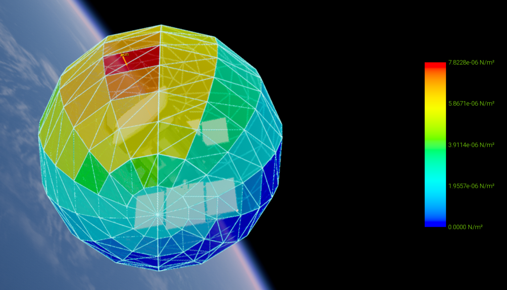
Show Solar Perturbation (checkbox)
Displays the solar radiation pressure distribution acting on the spacecraft surface.
The visualization represents force per unit area applied locally to each mesh element.
Show Aerodynamic Perturbation (checkbox)
Displays the aerodynamic pressure distribution acting on the spacecraft surface due to atmospheric interaction.
The visualization represents force per unit area applied locally to each mesh element.
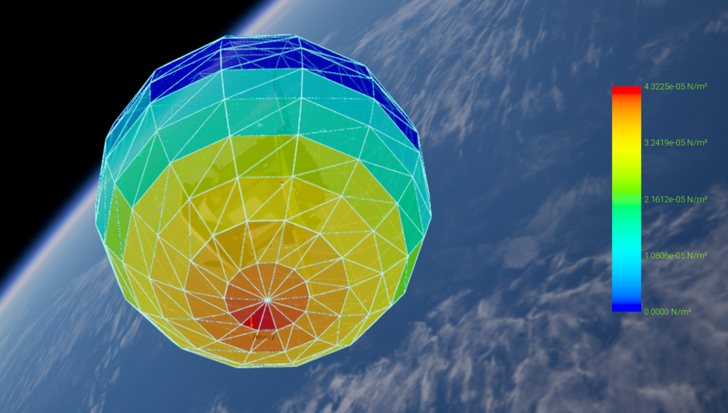
In both cases, perturbations are visualized using a color-coded surface mesh mapped directly onto the spacecraft geometry.
Colors indicate the relative magnitude of the local pressure load, not the total force acting on the spacecraft.
The resulting total forces and torques are computed internally by integrating these pressure distributions over the full spacecraft surface.
Perturbation Mesh Opacity (slider)
Controls the transparency of the perturbation mesh.
This allows simultaneous visualization of:
- The spacecraft shape mesh
- The perturbation pressure distribution
This overlay is especially useful when the perturbation mesh differs from the spacecraft shape mesh, as it highlights surface regions experiencing higher pressure loads or increased environmental exposure.
How to Use
- Use the toolbar to control playback speed, pause the simulation, or jump to a specific time.
- Enable reference frames and vectors in Display Config to understand spacecraft orientation and motion.
- Select camera presets in Camera to inspect the spacecraft from meaningful physical viewpoints.
- Toggle perturbation meshes in S/C Data to visually analyze solar and aerodynamic forces (if desired).
- Adjust the timeline slider to scrub through the simulation and observe dynamic changes over time.
Orbit View is intended to be used continuously during simulation setup, validation, and analysis, providing immediate visual feedback on spacecraft dynamics and environmental interactions.